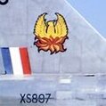
Mozart Posted August 19, 2020 Share Posted August 19, 2020 (edited) I've been doing the serial numbers for my Lightning this morning so here's the way that I went about it, but firstly a reminder of the main tools: I scanned the decal sheet that came with the kit and put the image into my photographs folder. then dragged the image into the Silhouette drawing area, scaling the image to a convenient size and clicking "send to back" (top tool bar) so that I could draw over it. I'm doing XS901, so I could trace the X and S and the 9. I started with the 9. The centre looked circular to me so I selected the line/circle tool and drew the inner. I copied this and enlarged it for the outer concentric circle. I grouped these two together, copied and pasted and moved this below the first circles: I used the straight line tool for the small horizontal on the 9's "tail" and a couple of verticals on the back of the 9: Then with the erasure tool I started to get rid of unnecessary bits - take the erasure tool close to the line but not too close at this stage. When I'd cleaned up most lines I went to an increased zoom for the detailed clean up - I moved the verticals slightly to one side then erased the curved line: then replaced the vertical, adjusting its length slightly if necessary. Within no time, the 9 was complete: Click on all line elements whilst holding Cmd+Shift and go to Group items then click for your finished 9. The S needed a bit more thought and a different procedure because there was no symmetry in any axis. So on the line select tool I chose the icon that looks like a figure 8 on its side, the curve drawing tool. Again remember I'm tracing over the decal onscreen. Click on the start point then click frequently following the outside line, more frequently on tighter curves. Be as accurate as possible but adjustment is easy later if you're slightly off: Stop where the curve meets a straight line, this tool will not go round sharp corners! Add the horizontals, if you go wrong at any point just go to the edit tool on the top tool bar and click on the undo button: If you want to fine tune your lines double click on the line and you'll then be able to move each point as much or little as you want to produce that smooth line. If you're working as I do to an enlarged screen any small variations will disappear as you reduce scale/size. Again finish by grouping all the elements and saving. For the X I traced one half of it. When drawing straight lines when you come to a corner do a quick double click to continue drawing in an "uninterrupted" way with a double click when you end. I grouped these lines: copied and pasted: then went to Object on the top tool bar, selected Mirror horizontally from the drop down menu: then moved the two halves together and grouped: The number "1" was very straightforward! The 0 could be done in different ways; clicking around its perimeter as with the S or drawing as with the 9. I copied the 9, ungrouped all the line elements then copied the longer vertical on the back, pasting this on the front side of the shape: Then with the erase tool I took out all unnecessary elements as before, re-grouped all and saved. I then assembled "XS901" together, grouped all and scaled to the correct size. The underwing serial was complete, from a further copy I scaled to the fuselage size, job done! The stencil was cut using Oramask 810 with a blade setting of 2, force 4, speed 5, 1 pass. Hope this has been useful to those of you new to cutters. Max Edited August 19, 2020 by Mozart 11 2 Quote Link to comment Share on other sites More sharing options...
Out2gtcha Posted August 19, 2020 Share Posted August 19, 2020 (edited) Another great Tut Max! About the same way as I do it. Well done (but not "nice" 😄) Edited August 19, 2020 by Out2gtcha 1 Quote Link to comment Share on other sites More sharing options...
Mozart Posted August 19, 2020 Author Share Posted August 19, 2020 Cheers Brian, "nice" one!! 😃 1 Quote Link to comment Share on other sites More sharing options...
Kevin Futter Posted August 19, 2020 Share Posted August 19, 2020 Can all this be done with the Basic Edition of the software, Max, or do you need one of the paid upgrade editions? Kev Quote Link to comment Share on other sites More sharing options...
Mozart Posted August 19, 2020 Author Share Posted August 19, 2020 (edited) The Designer edition is necessary to import images Kev. Drawing from scratch is the only way with the basic software but the small fee for the Designer software opens up so many avenues which increases the usefulness of the cutter tenfold. Edited August 19, 2020 by Mozart 2 Quote Link to comment Share on other sites More sharing options...
Kevin Futter Posted August 19, 2020 Share Posted August 19, 2020 Thanks, Max. I guess I'll have to upgrade at some point soon. I need to use the thing at all, first! My current project features some damaged USAF code letter decals, so that looks like a good place to start. Kev 1 Quote Link to comment Share on other sites More sharing options...
Mozart Posted August 19, 2020 Author Share Posted August 19, 2020 12 minutes ago, Kevin Futter said: Thanks, Max. I guess I'll have to upgrade at some point soon. I need to use the thing at all, first! My current project features some damaged USAF code letter decals, so that looks like a good place to start. Kev It’s so well worth the upgrade Kev. In all honesty I think that software should come as standard but at least it’s not too expensive. 2 Quote Link to comment Share on other sites More sharing options...
RadBaron Posted September 25, 2020 Share Posted September 25, 2020 Awesome writeup, Max, thankyou! 1 Quote Link to comment Share on other sites More sharing options...
AlbertD Posted October 25, 2020 Share Posted October 25, 2020 Thanks Max. Stuff like this will sure be a huge help to get a good start when I get mine. I can hardly wait. 1 Quote Link to comment Share on other sites More sharing options...
dashotgun Posted December 14, 2020 Share Posted December 14, 2020 hm the new basic lets you import jpgs and others now, have you tried using type faces? there are a lot of ttf which are usaf din raf etc 1 Quote Link to comment Share on other sites More sharing options...
IainM Posted January 3, 2021 Share Posted January 3, 2021 That's a great tutorial, thank you!! Lots of interesting gen in there! 1 Quote Link to comment Share on other sites More sharing options...
mgbooyv8 Posted January 5, 2021 Share Posted January 5, 2021 (edited) That's a great tutorial! Let me add my two cents as well, i hope its OK, otherwise I'll ask Kev to move this post. I received my Silhouette Portrait 3 recently and am learning the software now. With the Basic Edition that comes with the Portrait 3 you can now import pictures and trace them. I'm making masks for the registration letters for a model of a Dutch civil general aviation plane (1/20 Fuji FA-200). On the dutch government website, articles about the prescribed letter font and -distance can be found. These include pictures of very crappy scans of the letters and numbers on grid. So I'm learning the software by tracing the required letters. Like everybody else, I found out that you cannot weld different lines and curves together to get a closed shape for cutting. What I found out is that the point editor is a very powerful editing tool. This is my approach: - import the picture - enlarge it to obtain a very large letter, conform the recommendation of Max - in the line editor, select a closed polygon or closed curved shape: - trace the curved sections with many points cf. the recommendation of Max - trace the straight sections with only two points, from edge to edge. - if a curved closed shape is selected, ignore the deformation over the straight segments, this will be dealt with later with the point editor! - close the shape Now the point editor. If you have enabled the point editor, and selected a point with your mouse, you can open a submenu by clicking the right mouse button: Apologies about the Dutch language in the submenu. In this picture, I have selected a point somewhere in the curved section of a "P" What it says, you can select: - For the highlighted (bold) line segment betwee a straight line segment ("Maak recht") or a curved line segment ("Maak krom") This means you can make a curved line segment straight or vice versa. - Between a corner point ("hoek") or a smooth? point ("soepel"); corner point selected. With a corner point, you can alter the corner between two line segments. Therefore, you use the two "arms" connected to the point, and ending in the blue squares. In this picture, the "arms are directed to the right, disturbing the shape of the curve: You can move the arms by hovering the mouse over the blue squares and left mouse button pressed. Note that the arms can vary inlength! And align the arms in the desired direction of the line: Job done! Play with it, I hope this helps! Cheers, Peter Edited January 5, 2021 by mgbooyv8 pushed submit button too soon. 3 1 Quote Link to comment Share on other sites More sharing options...
Mozart Posted January 6, 2021 Author Share Posted January 6, 2021 Thanks Peter, I didn’t realise those arms could be used like that, it makes life considerably easier! 👍 Max 1 Quote Link to comment Share on other sites More sharing options...
mgbooyv8 Posted January 6, 2021 Share Posted January 6, 2021 You're welcome Max. This feature is similar to the point editor in CAD programme Rhino3D, which I'm familiar with. That's why I recognized its usefulness. 🙂 Cheers, Peter 1 Quote Link to comment Share on other sites More sharing options...

Recommended Posts
Join the conversation
You can post now and register later. If you have an account, sign in now to post with your account.
Note: Your post will require moderator approval before it will be visible.